

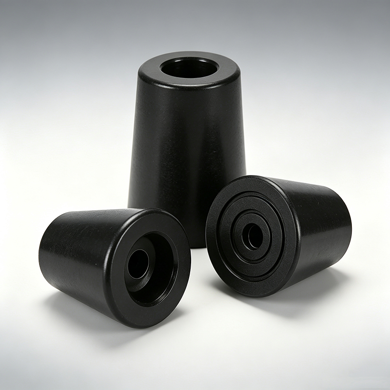
Choosing silicone feet for your equipment seems straightforward until you realize the wrong type can cause assembly problems, stability issues, or field failures.
Silicone feet come in several main types: cylindrical, conical, dome-shaped, flat, adhesive-backed, screw-mounted, threaded, and anti-vibration designs. Each type serves different load, mounting, and stability requirements, making proper selection critical for equipment performance.
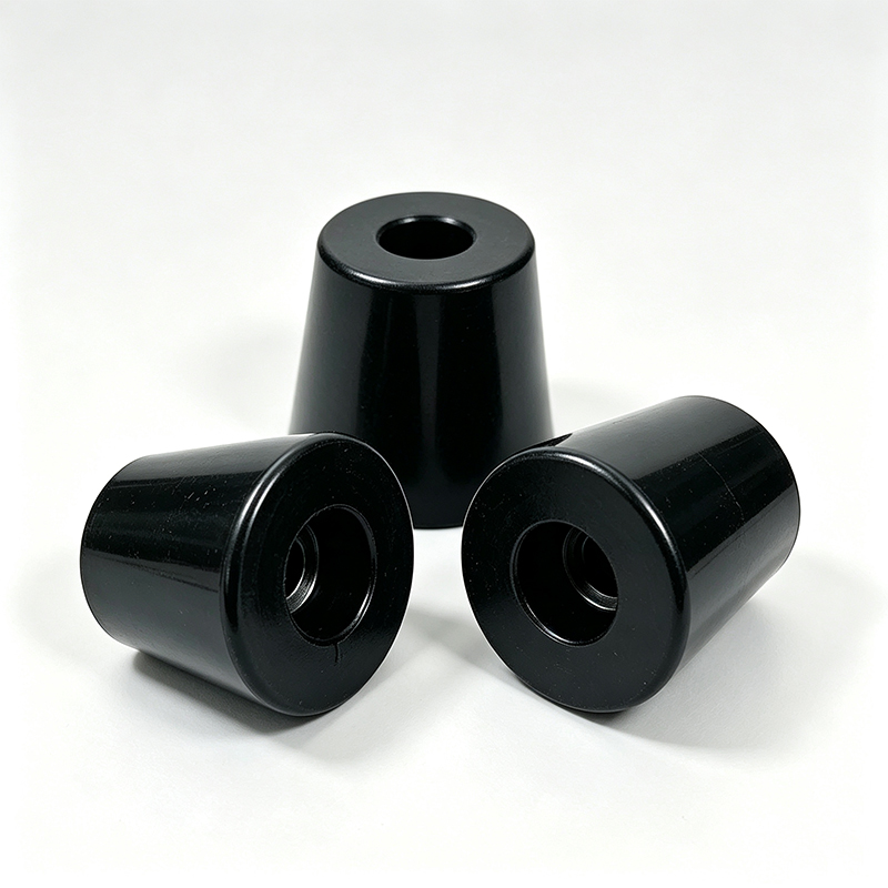
After 27 years in rubber component manufacturing, I have seen too many projects select silicone feet based only on dimensions. This approach works for simple applications but creates risks when the feet must control equipment movement, vibration, or mounting security.
Why Do Most Engineers Treat Silicone Feet as Interchangeable?
The biggest mistake happens when engineering teams assume similar-looking silicone feet perform the same function.
Engineers often select silicone feet by comparing external dimensions, mounting holes, and appearance without evaluating their actual mechanical performance under load. This leads to compression problems, stability issues, and mounting failures during production.


I recently worked with a customer who selected cylindrical silicone feet for their industrial control enclosure. The feet looked identical to the original specification. However, the wall thickness was different. Under the actual equipment load, these feet compressed 40% more than expected. The equipment clearance changed, and lateral movement increased during vibration.
The problem was not defective silicone. The problem was treating feet with similar external dimensions as functionally equivalent. Silicone feet are mechanical interfaces. Their performance depends on geometry, wall thickness, hardness, contact area, and mounting structure. Changes in any of these factors can alter how your equipment behaves after assembly.
A taller silicone foot may provide required clearance but create greater lateral movement. A softer foot may provide better cushioning but compress more under load. A larger contact area may reduce surface pressure but change friction and deformation characteristics. An adhesive silicone foot may work during prototype assembly but fail when production surface preparation varies.
The correct approach is to define functional requirements first, then select the silicone foot type that meets those requirements. External dimensions alone are insufficient for engineering decisions.
What Are Cylindrical Silicone Feet Best Used For?
Cylindrical silicone feet have a simple round body and represent the most common type for equipment support applications.
Cylindrical silicone feet work best for lightweight to medium-weight equipment requiring predictable vertical support with minimal lateral movement. They provide consistent contact geometry and are available in solid, screw-mounted, insert-mounted, and adhesive-backed configurations.
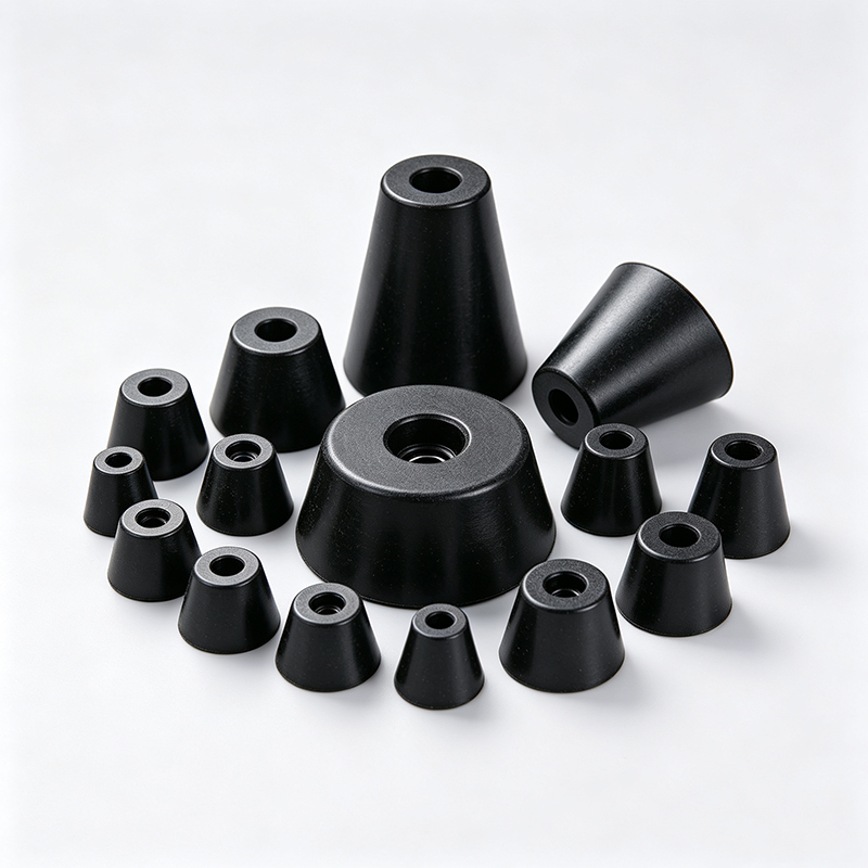
These feet are suitable for electronic devices, small appliances, instruments, control boxes, equipment housings, and desktop products. The circular geometry provides relatively predictable contact interface behavior. However, proper selection still requires evaluating vertical load, compression characteristics, contact diameter, height-to-diameter ratio, and mounting method.
I have manufactured cylindrical silicone feet for applications ranging from sensitive electronic instruments to industrial control panels. The key engineering consideration is the relationship between height and diameter. A tall, narrow cylindrical foot may provide good clearance but can become unstable under lateral forces. A short, wide foot provides better stability but may not offer sufficient clearance or cushioning.
The compression behavior also varies significantly with wall thickness and silicone hardness. A solid cylindrical foot will compress differently than a hollow version with the same external dimensions. For screw-mounted versions, the insert position and retention method affect both mounting security and compression characteristics.
Material selection matters as well. Shore A 40 silicone will behave very differently from Shore A 70 silicone under the same load. The softer material provides better vibration isolation but may compress excessively. The harder material maintains height better but transmits more vibration.
When specifying cylindrical silicone feet, I recommend defining the maximum allowable compression under actual equipment load. This prevents selecting a foot that looks correct but compresses beyond acceptable limits during operation.
How Do Conical and Tapered Silicone Feet Control Deformation?
Conical and tapered silicone feet use changing cross-sections to influence compression and stability characteristics.
Tapered silicone feet provide controlled deformation by gradually changing the contact area under load. This design offers better stability than cylindrical feet while maintaining cushioning properties, making them ideal for equipment requiring both support and vibration dampening.
The tapered geometry allows engineers to tune the compression response. As load increases, more of the tapered surface contacts the supporting surface. This progressive contact provides increasing stability while maintaining initial cushioning. The design is particularly useful for equipment housings, appliances, industrial devices, and vibration-sensitive structures.
I have designed tapered silicone feet for customers who needed specific compression profiles. One application required soft initial contact for vibration isolation but firm support at higher loads. The tapered design provided exactly this behavior. The narrow top section compressed easily under light loads, providing vibration dampening. As load increased, the wider base section engaged, providing stable support.
The main engineering risk with tapered feet is substitution. A supplier may propose replacing a tapered foot with a cylindrical version because overall height and diameter appear similar. This substitution should never be approved without functional testing. The compression and stability behavior will change significantly.
Taper angle affects performance dramatically. A steep taper provides rapid transition from soft to firm support. A gentle taper provides more gradual transition. The correct taper depends on the specific load profile and stability requirements of your equipment.
Manufacturing consistency is also critical for tapered feet. Small variations in taper angle or wall thickness can create significant performance differences. I always recommend specifying taper angle tolerance and requiring compression testing on production samples.
When Should You Choose Dome-Shaped Silicone Feet?
Dome-shaped silicone feet feature curved contact surfaces designed for controlled deformation and cushioning applications.
Dome-shaped silicone feet excel in applications requiring compliant contact points rather than rigid support. They provide excellent cushioning and surface protection but can deform significantly under load, making them suitable for lightweight equipment and covers.
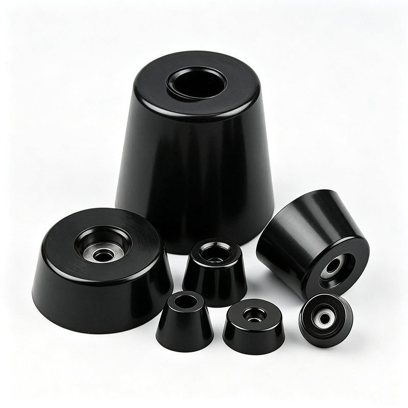
These feet are commonly found on electronic devices, instrument panels, lightweight equipment, covers, and small appliances. The dome geometry produces relatively significant deformation under load, which can be beneficial for cushioning but may cause problems if excessive.
I have supplied dome-shaped feet for sensitive electronic equipment where surface protection was critical. The curved contact surface distributed load evenly and prevented point contact damage to delicate surfaces. However, the same dome shape that provided excellent surface protection also created substantial height variation under different loads.
The main engineering consideration with dome-shaped feet is deformation control. Excessive deformation can cause height variation, increased movement, uneven support, and instability. The dome should be evaluated under actual installed load rather than just unloaded dimensions.
Dome geometry also affects lateral stability. A high, narrow dome may provide excellent cushioning but poor lateral stability. A low, wide dome provides better stability but less cushioning effect. The optimal dome profile depends on your specific balance between cushioning and stability requirements.
Material hardness becomes especially important for dome-shaped feet. Soft silicone enhances the cushioning effect but increases deformation. Hard silicone maintains height better but reduces cushioning. I typically recommend testing multiple hardness options to find the optimal balance for each application.
Surface finish also matters for dome-shaped feet. The curved contact surface concentrates stress, making surface defects more problematic than with flat feet. Manufacturing processes must maintain smooth, consistent dome profiles to prevent premature failure or uneven contact.
What Makes Flat Silicone Feet Different from Other Types?
Flat or disc-shaped silicone feet provide broad contact surfaces designed to minimize surface pressure and maximize stability.
Flat silicone feet distribute load over larger contact areas, reducing surface pressure and providing stable support with relatively low profiles. They are ideal for applications requiring surface protection, stable contact, and minimal height addition to equipment.
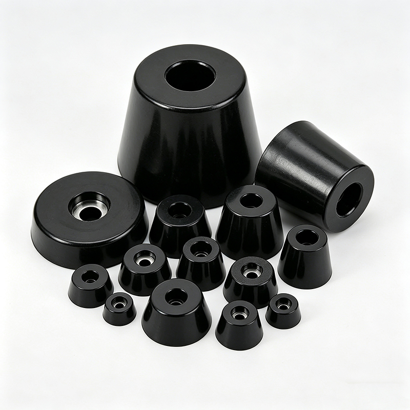
These feet work well for electronic housings, control panels, appliances, office equipment, and lightweight industrial devices. The large contact area provides several advantages: reduced surface pressure, improved stability, better load distribution, and enhanced surface protection.
I have manufactured flat silicone feet for customers who needed to protect sensitive surfaces while maintaining equipment stability. One application involved precision measurement equipment that required stable support on polished granite surfaces. Flat silicone feet provided the necessary surface protection while maintaining the stability required for accurate measurements.
However, large contact area does not automatically guarantee better performance. The result still depends on the combination of contact area, silicone hardness, load, surface condition, and foot geometry. If the silicone is too soft, the foot may deform substantially despite its large contact area. If too hard, the intended cushioning effect may be reduced.
Adhesion can become an issue with flat feet. The large contact area can create substantial adhesive forces, especially on smooth surfaces. This can make equipment difficult to move or reposition. Some applications require adding texture or reducing contact area to prevent excessive adhesion.
Edge effects also matter for flat feet. Sharp edges can concentrate stress and cause premature failure or surface damage. I recommend specifying rounded edges or chamfers to prevent these problems. The edge radius should be large enough to eliminate stress concentration but small enough to maintain the desired contact area.
Thickness uniformity is critical for flat feet. Variations in thickness create uneven load distribution and can cause rocking or instability. Manufacturing processes must maintain consistent thickness across the entire contact surface.
Why Are Adhesive Silicone Feet More Complex Than They Appear?
Adhesive silicone feet attach directly to product surfaces using adhesive layers, eliminating the need for mechanical fasteners.
Adhesive silicone feet create a functional system combining silicone, adhesive, substrate, and assembly process. Success depends on all four elements working together, making them more complex than mechanically mounted alternatives but ideal for applications without fastener access.
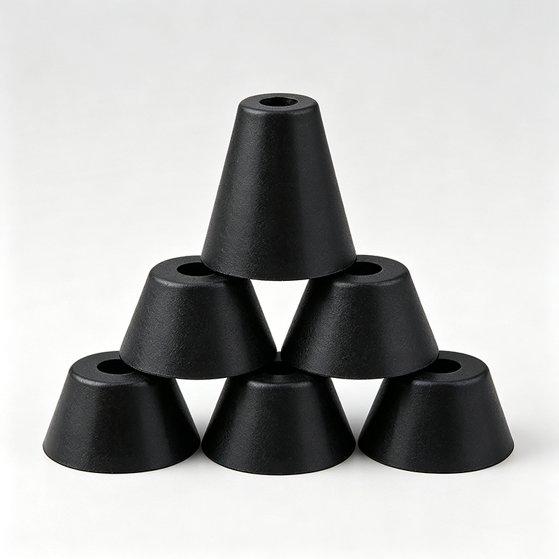
These feet are commonly used on consumer electronics, small appliances, electronic housings, lightweight instruments, and desktop equipment. They provide clean appearance without visible fasteners and work well when the product design lacks space for screws or other mechanical mounting methods.
The engineering challenge with adhesive feet is system complexity. The silicone itself may perform perfectly while the overall attachment system fails. I have seen projects where identical silicone feet worked perfectly in prototypes but failed in production due to substrate preparation differences.
Critical variables include substrate material compatibility, surface contamination levels, surface preparation consistency, adhesive compatibility with both silicone and substrate, application pressure during installation, installation time and temperature, operating temperature range, and shear and peel loading conditions.
Substrate preparation is often the weakest link. Prototype assemblies typically receive careful surface cleaning and preparation. Production assemblies may have oil residues, handling contamination, or inconsistent cleaning procedures. These variations can dramatically affect adhesive performance.
I always recommend validating adhesive feet using actual production substrates and assembly processes. Laboratory adhesion testing on clean samples may not represent production conditions. The validation should include aging tests to verify long-term adhesion under operating conditions.
Temperature effects can also surprise engineers. Adhesives that work well at room temperature may fail at elevated operating temperatures or during temperature cycling. Silicone thermal expansion can create additional stress on the adhesive bond.
Removal and replacement should be considered during design. Some adhesive systems create permanent bonds that damage the substrate during removal. Others allow clean removal but may not rebond effectively. The choice depends on service requirements and product lifecycle expectations.
How Do Screw-Mounted Silicone Feet Provide Better Security?
Screw-mounted silicone feet use mechanical fasteners to attach silicone components to equipment, providing more secure attachment than adhesive alternatives.
Screw-mounted silicone feet offer reliable mechanical attachment independent of surface preparation or adhesive aging. They work well for industrial equipment, heavier loads, and applications requiring field serviceability, but require access holes and proper fastener selection.


These feet are suitable for industrial equipment, electronic enclosures, appliances, control cabinets, and instruments where secure mounting is required. The mechanical interface provides predictable attachment that does not depend on adhesive chemistry or surface preparation.
The main advantage is mechanical definition rather than relying on adhesive attachment. However, the mounting system must be evaluated as a complete assembly. I have worked with customers who selected appropriate silicone feet but encountered problems with the mounting hardware or installation process.
Important variables include screw size compatibility with equipment design, mounting hole dimensions and tolerances, insert position and retention within the silicone, fastening torque requirements and limits, compression of silicone during installation, and access requirements for assembly and service.
Insert design affects both performance and manufacturing. Metal inserts provide strong threads but require careful positioning during molding. Molded threads in the silicone itself may be sufficient for light loads but can strip under excessive torque. The choice depends on load requirements and assembly conditions.
Compression control becomes critical with screw mounting. Over-tightening can compress the silicone excessively, reducing its cushioning properties and potentially causing premature failure. Under-tightening may allow the foot to work loose during operation. I recommend specifying installation torque limits and providing clear assembly instructions.
Thread locking may be necessary for applications with vibration or thermal cycling. However, thread locking compounds must be compatible with silicone materials. Some compounds can cause silicone degradation over time.
Access for assembly and service should be considered during design. Screw-mounted feet may require access from inside the equipment enclosure, which can complicate assembly or field service. The mounting design should balance security with practical assembly requirements.
What Special Considerations Apply to Threaded Silicone Feet?
Threaded silicone feet incorporate threaded studs or inserts to provide secure mounting with height adjustment capability.
Threaded silicone feet combine mechanical mounting security with height adjustability, making them ideal for industrial equipment requiring leveling or precise height control. However, they introduce additional variables that must be controlled to maintain stability and performance.
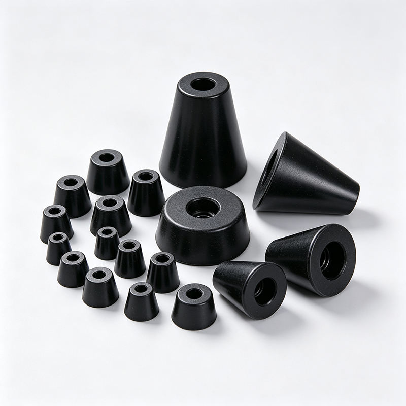
These feet are often used on industrial machinery, equipment frames, cabinets, laboratory equipment, and adjustable equipment bases. They provide secure mechanical mounting combined with the ability to adjust height for leveling or clearance requirements.
The main project risk with threaded feet is the additional mechanical variable introduced by adjustment capability. If the foot extends too far, equipment stability may decrease even though the silicone component remains intact. I have seen installations where individual feet were adjusted incorrectly, creating equipment instability or uneven load distribution.
Engineering teams must define minimum thread engagement requirements, maximum adjustment range, allowable installation height variation, load conditions across the adjustment range, and stability requirements at all positions. Testing only the nominal adjustment position is insufficient when the product can be installed across a range of heights.
Thread engagement becomes critical for load capacity. As the foot extends, less thread engages with the mounting surface, reducing load capacity. The design must ensure adequate thread engagement at maximum extension under worst-case loading conditions.
Stability analysis should consider the highest adjustment position. Extended feet create a higher center of gravity and may reduce lateral stability. The analysis should include both static stability and dynamic response to vibration or impact loading.
Lock nuts or thread locking may be necessary to prevent adjustment drift during operation. Vibration or thermal cycling can cause threaded feet to gradually change position if not properly secured. However, locking mechanisms must not prevent intentional adjustment during installation or service.
Installation procedures become more complex with threaded feet. Assembly personnel must understand proper adjustment procedures, thread engagement requirements, and stability considerations. Clear installation instructions and training are essential for consistent results.
I recommend providing adjustment limits or mechanical stops to prevent over-extension. These can be built into the foot design or specified as installation procedures. The goal is to prevent field personnel from creating unsafe conditions through improper adjustment.
How Can You Avoid Common Selection Mistakes with Silicone Feet?
Most silicone foot selection problems stem from incomplete functional requirements rather than defective components.
Successful silicone foot selection requires defining load conditions, compression limits, stability requirements, mounting methods, and environmental conditions before comparing options. Dimensional similarity alone is insufficient for engineering decisions.
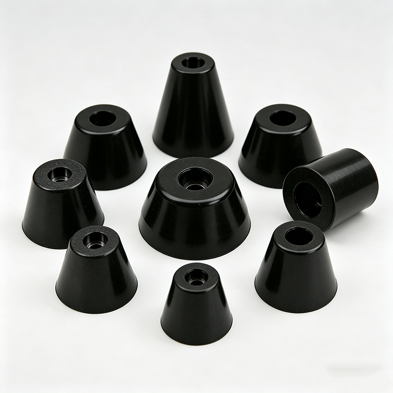
The most common mistake is selecting silicone feet by appearance and dimensions without understanding their functional requirements. This approach treats feet as catalog items rather than engineered components. The result is often assembly problems, performance issues, or field failures that could have been prevented with proper selection criteria.
I recommend starting every silicone foot selection with functional requirements: total equipment weight and load distribution, number of feet and load per foot, required equipment height and clearance, allowable compression under load, lateral stability requirements, vibration conditions and dampening needs, mounting method and access requirements, environmental conditions and temperature range, and service life expectations.
Load analysis should consider worst-case conditions, not just nominal values. Equipment weight may vary with different configurations or loading conditions. Load distribution may not be uniform, especially if the center of gravity is not centered among the feet. Dynamic loading from vibration or impact should also be considered.
Compression limits must be defined based on functional requirements rather than arbitrary percentages. Some applications can tolerate significant compression if height variation is acceptable. Others require minimal compression to maintain precise clearances or alignments.
Stability analysis should include both static and dynamic conditions. Static stability considers resistance to tipping under normal loading. Dynamic stability considers response to vibration, impact, or lateral forces during operation or handling.
Environmental conditions affect both silicone performance and mounting systems. Temperature cycling can cause dimensional changes and stress on mounting interfaces. Chemical exposure may affect silicone properties or adhesive bonds. UV exposure can cause degradation in some silicone formulations.
Testing should represent actual operating conditions rather than ideal laboratory conditions. Prototype testing with carefully prepared samples may not represent production assembly conditions or field installation environments.