

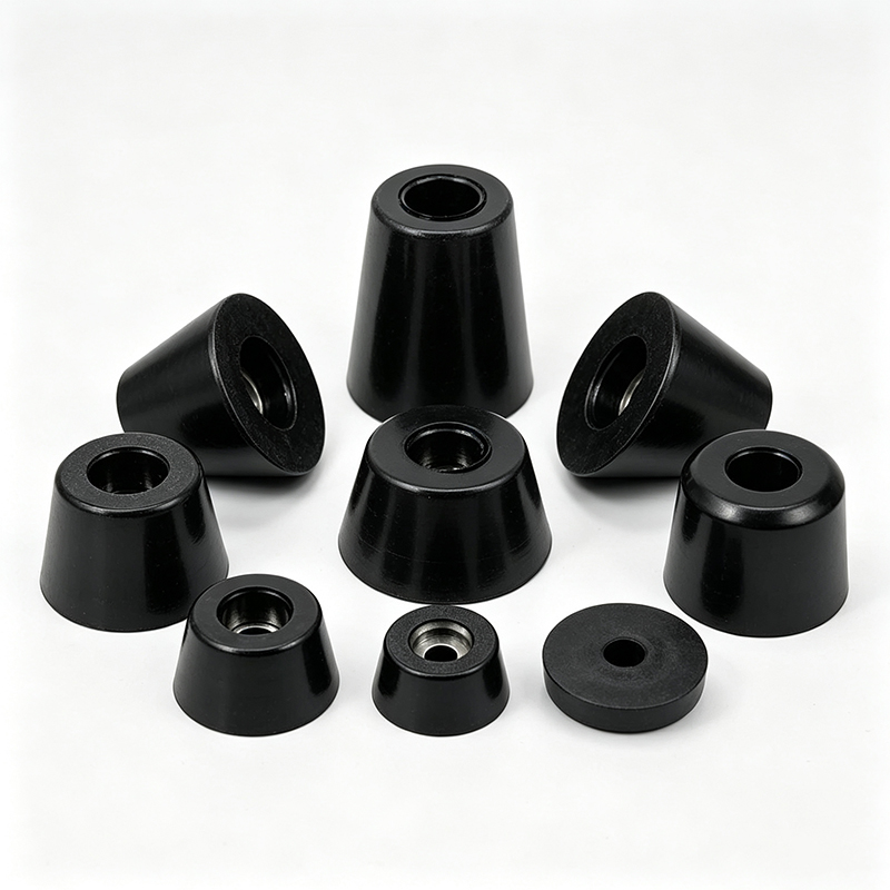
Ever wondered why your equipment keeps sliding or why vibrations keep transferring through your machinery? You're not alone in facing these challenges.
Rubber feet offer multiple engineering benefits including vibration isolation, anti-slip performance, surface protection, shock absorption, and equipment stability. However, these benefits only materialize when the material properties, geometry, and mounting method match your specific application requirements.
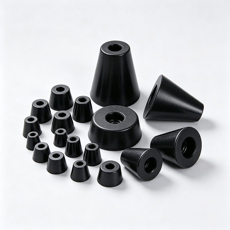
At our factory, I've seen countless projects where teams assume rubber feet automatically solve stability problems. The reality is more complex. Let me share what we've learned from 27 years of manufacturing experience.
Does Material Selection Really Impact Performance?
Many engineers think any rubber will work for their application. This assumption causes problems later.
The rubber compound directly determines load capacity, compression resistance, temperature tolerance, and chemical compatibility. EPDM works differently than silicone, and NBR behaves differently than natural rubber under the same conditions.
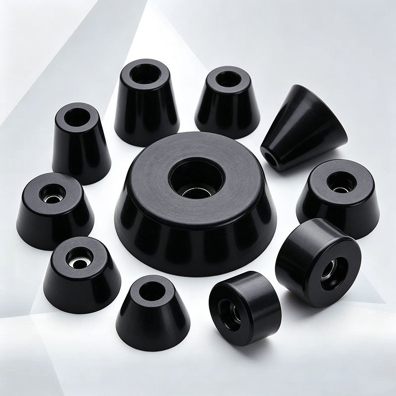
I remember a project where a customer specified "standard rubber feet" for outdoor equipment. We used natural rubber initially. After six months in UV exposure, the feet cracked and failed. We switched to EPDM compound with UV stabilizers. The replacement feet lasted over three years in the same conditions.
Material selection affects every performance aspect. Silicone handles extreme temperatures but costs more. NBR resists oils but degrades in ozone. EPDM provides weather resistance but may not grip as well on smooth surfaces. Each compound creates trade-offs.
The hardness also matters significantly. Shore A 40 rubber compresses easily but may deform permanently under heavy loads. Shore A 80 rubber supports more weight but transmits more vibration. We typically recommend Shore A 60-70 for general applications, but this varies based on your specific requirements.
Temperature range is another critical factor. Standard rubber compounds work from -20°C to +80°C. For extreme conditions, we use specialized compounds. One automotive client needed feet operating at -40°C. We formulated a custom blend with special plasticizers to maintain flexibility.
Can Rubber Feet Actually Prevent Equipment Movement?
Anti-slip performance depends on more factors than just using rubber material. Many projects fail because teams don't consider the complete contact interface.
Effective anti-slip performance requires proper contact area, appropriate rubber hardness, suitable surface texture, and adequate normal force. The coefficient of friction varies significantly based on floor material, cleanliness, and environmental conditions.
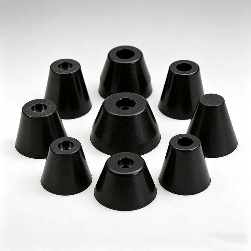
We tested identical rubber feet on different surfaces. On clean concrete, they provided excellent grip. On oily metal surfaces, the same feet slipped easily. The rubber compound wasn't the problem. The surface contamination was.
Contact area plays a huge role. A small foot concentrates the load but may not provide enough friction force. A large foot distributes the load but requires more mounting space. We calculate the required contact area based on equipment weight and expected horizontal forces.
Surface texture affects grip significantly. Smooth rubber may slide on polished floors. Textured surfaces increase friction but collect dirt more easily. We often mold fine patterns into the contact surface to balance grip and cleanability.
Load distribution matters too. If your equipment's center of gravity is offset, some feet carry more weight than others. The heavily loaded feet grip better, but the lightly loaded ones may slip. We sometimes recommend different foot sizes or hardnesses to balance the contact forces.
Environmental factors change performance over time. Dust reduces friction. Moisture can increase or decrease grip depending on the rubber compound. Temperature changes affect rubber flexibility. We test feet under your actual operating conditions whenever possible.
How Do Rubber Feet Control Vibration Transmission?
Vibration isolation requires understanding the mechanical system, not just adding soft rubber. Many teams select rubber that's too soft and create stability problems.
Effective vibration isolation depends on the resonant frequency relationship between the equipment mass, rubber stiffness, and excitation frequency. The rubber acts as a spring-damper system that must be tuned for your specific application.
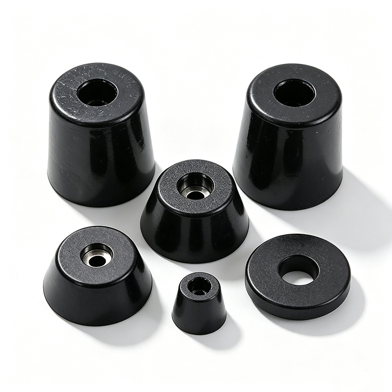
We learned this lesson with a precision instrument manufacturer. Their equipment contained high-speed motors that generated 3000 RPM vibration. They initially wanted very soft feet to "absorb everything." The soft rubber reduced vibration but allowed too much equipment movement during operation.
We calculated the system natural frequency using the equipment mass and rubber stiffness. The goal was to keep the natural frequency well below the excitation frequency. This required a specific rubber hardness that balanced isolation and stability.
The number of mounting points affects the system behavior. Four feet create different dynamics than six feet. We consider the load distribution and geometric stability when recommending the mounting configuration.
Rubber thickness influences both stiffness and stability. Thicker rubber provides more compliance but allows more movement. Thinner rubber supports the load better but transmits more vibration. We optimize the geometry based on your performance priorities.
Damping characteristics vary by compound. Some rubbers absorb energy well but compress permanently. Others maintain their shape but transmit more vibration. We select compounds that provide the right balance of isolation and longevity for your application.
What Protection Do Rubber Feet Provide for Surfaces?
Surface protection isn't automatic with rubber feet. The wrong design can actually cause more damage than metal contact.
Effective surface protection requires appropriate contact pressure, suitable rubber hardness, proper edge design, and consideration of movement patterns. Hard rubber or excessive loading can damage delicate surfaces despite using rubber material.
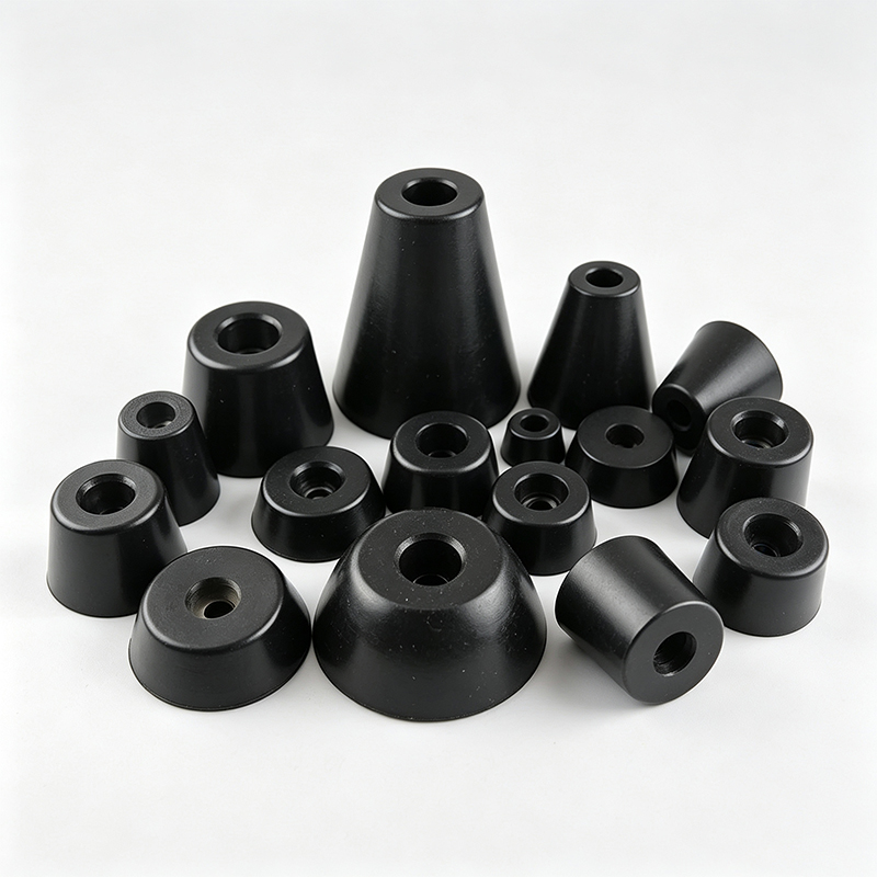
A furniture manufacturer learned this the hard way. They used small, hard rubber feet on heavy cabinets. The concentrated load created permanent impressions in wooden floors. We redesigned the feet with larger contact areas and softer rubber to distribute the load properly.
Edge design is critical for surface protection. Sharp edges concentrate stress even with soft rubber. We radius all edges that contact surfaces. The radius size depends on the rubber hardness and expected load.
Movement patterns affect wear characteristics. Equipment that slides occasionally needs different feet than stationary equipment. Rotating or vibrating equipment creates different wear patterns. We consider the actual usage when designing the contact interface.
Rubber hardness must match the surface sensitivity. Delicate finishes require softer rubber with larger contact areas. Rough surfaces can handle harder rubber with smaller footprints. We test actual contact pressure using pressure-sensitive film when surface protection is critical.
Contamination under the feet can cause problems. Dirt or debris trapped between the rubber and surface acts like sandpaper. We design feet with self-cleaning features or drainage channels when contamination is expected.
Do Rubber Feet Really Absorb Shock and Impact?
Shock absorption depends on the energy absorption capacity and recovery characteristics of the rubber compound. Not all rubber provides effective impact protection.
Effective shock absorption requires rubber compounds with high energy absorption, appropriate thickness for expected impact levels, and geometry that prevents bottoming out under maximum loads. Recovery speed affects equipment stability after impact.
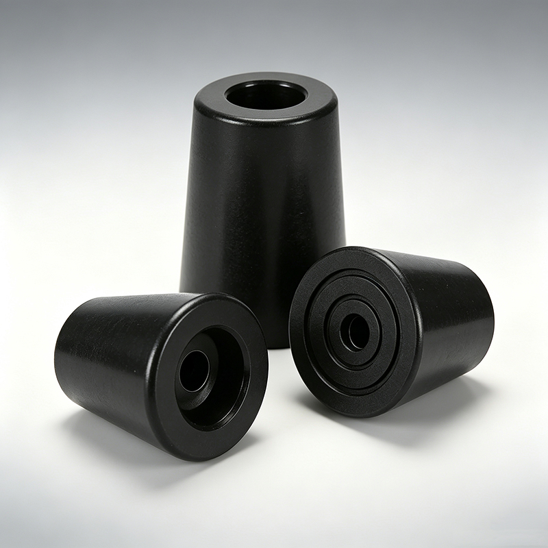
We tested this with a portable equipment manufacturer whose products were frequently dropped during transport. Standard rubber feet cracked under impact. We developed a two-stage design with soft outer rubber for impact absorption and firm inner support for load bearing.
Energy absorption varies significantly by compound. Natural rubber absorbs impact well but may not recover quickly. Silicone recovers rapidly but may not absorb as much energy. We select compounds based on your impact requirements and recovery needs.
Thickness affects both absorption and stability. Thicker rubber absorbs more energy but allows more equipment movement. We calculate the required thickness based on expected impact energy and acceptable deformation limits.
Geometry influences impact distribution. Cylindrical feet concentrate impact forces. Conical or spherical designs distribute forces more evenly. We optimize the shape based on your equipment's impact patterns and stability requirements.
Recovery characteristics affect repeated impact performance. Rubber that doesn't recover fully after impact provides less protection for subsequent impacts. We test recovery time and permanent deformation under your actual impact conditions.
How Do Rubber Feet Maintain Equipment Height and Clearance?
Maintaining proper clearance requires understanding compression characteristics under load. Many projects fail because teams don't account for rubber deformation.
Effective height control requires calculating rubber compression under actual loads, accounting for load distribution variations, and selecting appropriate hardness to maintain required clearance throughout the equipment's operating life.
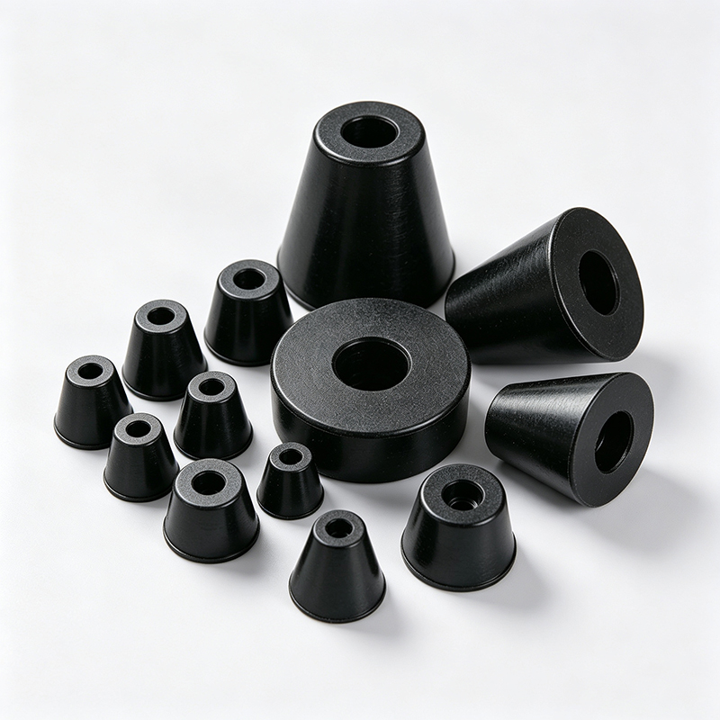
An electronics manufacturer specified 10mm clearance for airflow under their equipment. They selected rubber feet with 12mm unloaded height, assuming 2mm compression would be acceptable. Under actual load with uneven weight distribution, some feet compressed 8mm while others compressed only 3mm. The equipment tilted and blocked the airflow channels.
We solved this by calculating the compression for each foot position based on the equipment's center of gravity and mounting geometry. We specified different rubber hardnesses for different positions to achieve uniform compression and maintain level installation.
Load distribution affects compression patterns significantly. Equipment with offset components loads some feet more heavily than others. We analyze the weight distribution and specify foot properties accordingly.
Temperature affects rubber stiffness and compression. Cold rubber compresses less than warm rubber. We account for your operating temperature range when calculating compression characteristics.
Creep and stress relaxation cause compression to increase over time. Initial compression may be acceptable, but long-term deformation can reduce clearance below acceptable limits. We test long-term compression set under your actual loading conditions.
Conclusion
Rubber feet provide significant benefits when properly engineered for your specific application, but success requires matching material properties, geometry, and mounting methods to your actual requirements rather than assuming all rubber feet work the same way.