

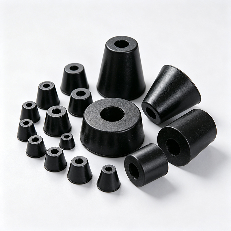
Choosing rubber feet often feels like a simple task. You check dimensions, find something that fits, and move forward. But then production starts and problems appear.
The right rubber foot selection requires understanding load distribution, compression behavior, and mounting stability - not just dimensional fit. A foot that matches your hole size can still fail catastrophically under real operating conditions.
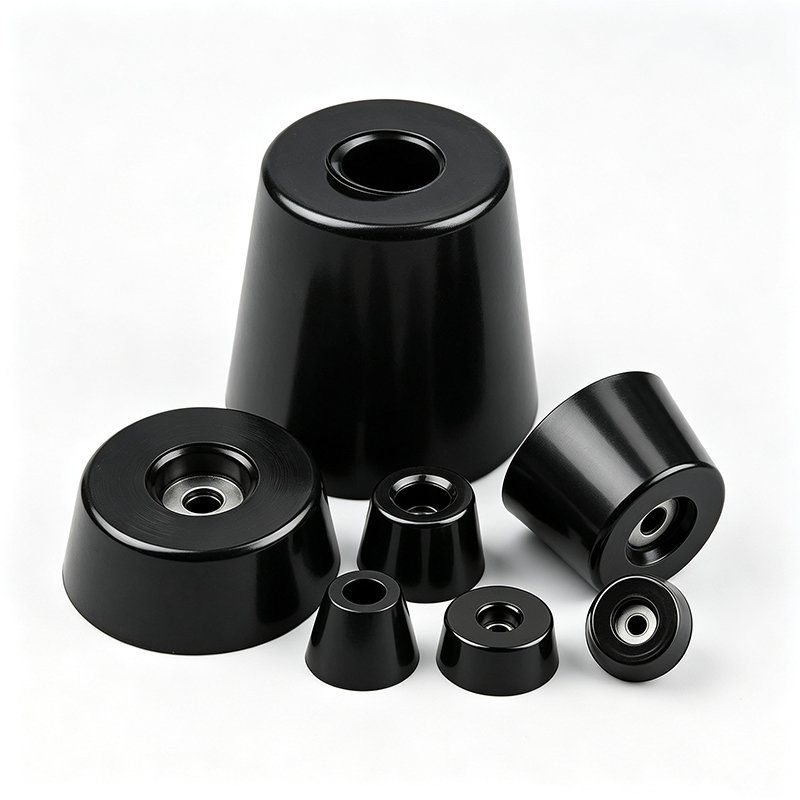
I have seen this mistake countless times in my 27 years in the rubber industry. Projects that looked perfect during sampling became expensive failures during mass production. The problem is not the rubber quality. The problem is treating component selection as a purchasing decision instead of an engineering decision.
What Makes Rubber Foot Selection So Deceptive?
Most selection failures start with a reasonable assumption. You have mounting holes, weight requirements, and height specifications. A standard rubber foot appears to match everything.
The deception happens because rubber feet perform multiple functions simultaneously: load bearing, vibration isolation, height adjustment, and equipment stability. Optimizing for one function can compromise the others.
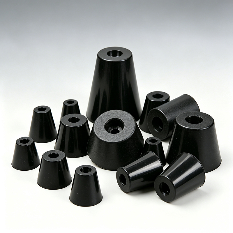
I remember a project where we supplied rubber feet for industrial control cabinets. The customer approved samples based on fit and appearance. During installation, they discovered the equipment could be rocked by hand. The problem was not our manufacturing quality. The problem was that nobody calculated the actual load distribution. The cabinet had heavy components positioned toward one side. Two feet carried most of the weight while the other two barely touched the floor.
This created a stability problem that only appeared during real installation. The customer had tested individual components but never tested the complete system under actual loading conditions. We had to redesign the feet with different compression characteristics and modify the mounting interface. The project succeeded, but the delay and rework could have been avoided with better initial analysis.
The lesson is that rubber foot selection requires system thinking. You are not just buying a component. You are designing a load transfer interface between your equipment and the installation surface.
How Do Load Requirements Actually Work in Practice?
The textbook approach says divide total weight by number of feet. This calculation is wrong for most real applications. Equipment rarely has perfectly centered weight distribution.
Real load analysis must account for center of gravity offset, dynamic loading during operation, and worst-case loading scenarios. The heaviest loaded foot determines your selection requirements, not the average load.
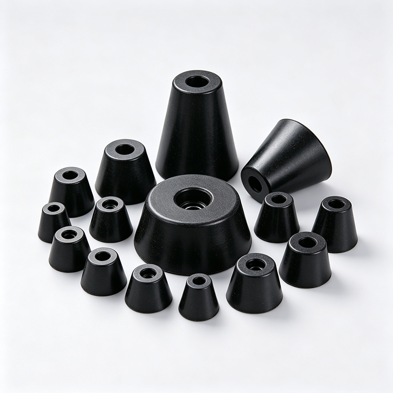
Here is how I approach load analysis for customer projects. First, I ask for the total equipment weight and approximate center of gravity location. Then I calculate the theoretical load distribution assuming the equipment sits on a perfectly flat surface. Next, I add safety factors for dynamic loading, vibration, and installation variations.
The critical insight is that floor surfaces are never perfectly flat. Even small variations create load concentration on individual feet. If your rubber foot selection assumes equal loading, you are designing for ideal conditions that do not exist in real installations.
| Load Analysis Factor | Typical Impact | Design Consideration |
|---|---|---|
| Center of gravity offset | 20-40% load variation | Calculate worst-case foot loading |
| Floor irregularities | 10-30% additional load | Add surface variation margin |
| Dynamic operation | 15-25% peak loading | Include vibration and movement |
| Installation tolerance | 5-15% variation | Account for assembly differences |
I also consider equipment operation patterns. Does the equipment have doors that open? Are operators interacting with controls? Is there cable movement that creates additional forces? These factors create dynamic loading that static calculations miss.
The goal is not perfect precision. The goal is understanding whether your rubber foot selection has adequate margin for real-world variations. A foot that works at 90% of its capacity during testing will fail when installation conditions add unexpected loading.
Why Does Rubber Hardness Matter More Than You Think?
Everyone asks about Shore A hardness first. This question reveals a fundamental misunderstanding about how rubber feet actually work. Hardness affects compression, but geometry affects load distribution.
A harder rubber foot reduces compression but may concentrate stress. A softer foot distributes load better but may compress excessively. The optimal choice depends on your specific stability and height requirements.


I have worked with customers who insisted on specific hardness values without understanding the trade-offs. One project required precise equipment height for alignment with other machinery. The customer wanted soft rubber for vibration isolation. But soft rubber compressed too much under load, making height control impossible.
We solved this by changing the geometry instead of just the hardness. A wider contact area with medium hardness rubber provided better height stability while still offering vibration isolation. The customer achieved both requirements without compromising either function.
The engineering approach is to define your functional priorities first. Do you need precise height control? Maximum vibration isolation? Minimum compression? Maximum load capacity? Different priorities lead to different hardness and geometry combinations.
| Application Priority | Recommended Approach | Typical Hardness Range |
|---|---|---|
| Precise height control | Medium-hard rubber, wide contact | 60-70 Shore A |
| Maximum vibration isolation | Soft rubber, optimized geometry | 40-55 Shore A |
| Heavy load capacity | Hard rubber, reinforced design | 70-80 Shore A |
| General purpose | Balanced compromise | 55-65 Shore A |
I also consider long-term compression set. Rubber feet gradually lose height under constant loading. Softer compounds show more compression set over time. If your application requires stable height for years of operation, this factor becomes critical for material selection.
The key insight is that hardness is one design variable in a multi-variable optimization problem. Changing hardness affects compression, load distribution, vibration isolation, and long-term stability simultaneously. Successful selection requires balancing all these factors for your specific application requirements.
What Installation Methods Actually Work Reliably?
Installation seems simple until you consider long-term reliability. A rubber foot that installs easily during assembly can become loose during operation. The mounting interface must transfer load while accommodating rubber compression and thermal expansion.
Threaded studs provide the most reliable attachment for heavy loads, but require precise hole alignment. Push-in designs offer easier installation but limited pull-out resistance. The choice depends on your load requirements and assembly constraints.


I have seen projects fail because the mounting method was selected for assembly convenience rather than operational reliability. One customer used push-in rubber feet for equipment that experienced significant vibration. The feet gradually worked loose and fell out during operation.
The problem was not the rubber quality or the installation procedure. The problem was that push-in mounting relies on friction and interference fit. Vibration reduces this retention force over time. For this application, threaded mounting would have been more appropriate despite the additional assembly complexity.
Here is my evaluation framework for mounting methods. First, I consider the maximum load and safety requirements. Equipment that could cause injury if it falls requires the most secure mounting possible. Second, I evaluate the installation environment. Field assembly has different constraints than factory assembly. Third, I consider maintenance requirements. Some applications need removable feet for cleaning or service access.
| Mounting Method | Load Capacity | Installation Ease | Long-term Reliability | Best Applications |
|---|---|---|---|---|
| Threaded stud | Highest | Moderate | Excellent | Heavy equipment, critical stability |
| Screw-through | High | Good | Very good | General industrial applications |
| Push-in | Moderate | Excellent | Good | Light equipment, easy removal needed |
| Adhesive | Low-Moderate | Good | Variable | Smooth surfaces, permanent installation |
The engineering consideration is that mounting reliability affects overall equipment safety. A rubber foot failure can cause equipment damage, product contamination, or operator injury depending on the application. The mounting method should be selected with appropriate safety margin for the consequences of failure.
I also recommend considering assembly training requirements. Complex mounting procedures increase the risk of installation errors. Simple, foolproof installation methods reduce field problems even if they require more engineering effort during design.
How Do You Test Rubber Feet Before Production?
Most companies test rubber feet by installing them and checking basic fit. This approach misses the most common failure modes. Effective testing must reproduce the actual loading and operating conditions.
Proper rubber foot testing requires applying maximum expected loads, measuring compression under sustained loading, and verifying stability under dynamic conditions. Visual inspection and basic fit checking are insufficient for reliable selection.


My standard testing protocol starts with static load testing. I apply 150% of the expected maximum load and measure compression after 24 hours. This reveals whether the rubber foot will maintain acceptable height under sustained loading. Many rubber compounds show significant creep under constant load that is not apparent during short-term testing.
Next, I test dynamic loading by applying cyclic loads that simulate equipment operation. This reveals fatigue behavior and mounting reliability under repeated loading. I also test installation and removal procedures to verify that the mounting method works consistently without damaging the rubber or the equipment.
The most important test is system-level validation. I install the rubber feet on representative equipment and verify stability under actual operating conditions. This includes checking whether the equipment can be moved by hand, whether it remains stable during door operation, and whether height remains consistent across all mounting points.
| Test Type | Duration | Load Level | Measurement | Pass Criteria |
|---|---|---|---|---|
| Static compression | 24 hours | 150% max load | Height change | <10% compression |
| Dynamic cycling | 10,000 cycles | 100% operating load | Fatigue resistance | No visible damage |
| Installation test | 10 cycles | Assembly force | Installation consistency | Repeatable procedure |
| System validation | Full operation | Real conditions | Equipment stability | Meets functional requirements |
I document all test results and provide them to customers as part of the engineering package. This creates objective evidence that the selected rubber foot will perform reliably in the application. It also provides a baseline for quality control during production.
The goal is not just to prove that the rubber foot works. The goal is to demonstrate that it works with adequate safety margin under all expected operating conditions. This approach prevents field failures that could compromise equipment performance or safety.
Conclusion
Successful rubber foot selection requires engineering analysis, not just dimensional matching. Define your load requirements, test under real conditions, and verify long-term reliability before production commitment.