

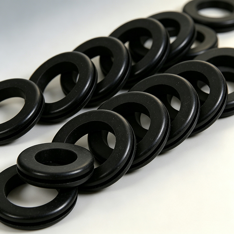
Getting gasket dimensions wrong can turn a simple sealing project into a production nightmare with leaks, rework, and angry customers.
To calculate gasket size correctly, you need more than basic math. You must understand your sealing mechanism, compression requirements, manufacturing tolerances, and assembly conditions before picking any numbers.
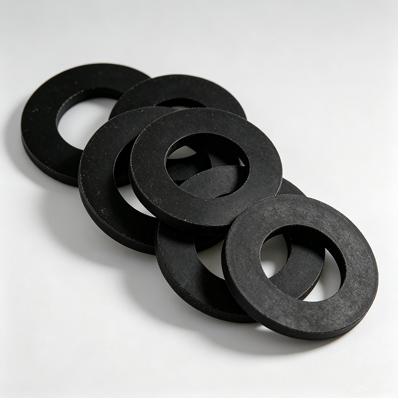
Most engineers make the same mistake. They measure an opening, add some rubber width, and call it done. This approach works fine until mass production starts and real tolerances kick in.
Why Do Most Gasket Size Calculations Fail in Production?
Calculating gasket dimensions looks straightforward until you face real assembly conditions and manufacturing variation.
The biggest mistake is not calculation errors. It's using the wrong calculation logic for your actual sealing application.
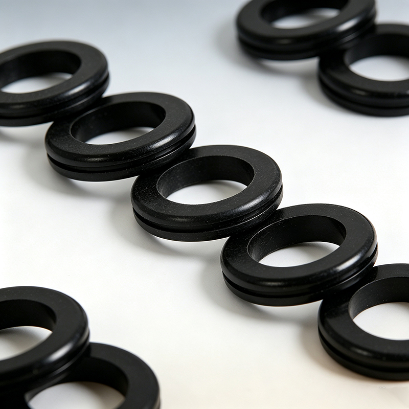
I've seen countless projects where gaskets passed dimensional inspection but still leaked. The problem wasn't the math. It was the engineering assumptions behind the math. Here's what typically goes wrong:
Most teams start with the available opening and work backward. They measure a sealing opening, add gasket width, and define dimensions as: ID + gasket width + gasket width = OD. The calculation is mathematically correct, but the engineering logic is flawed.
Gasket dimensions depend on much more than the opening size. You need to consider sealing surface width, groove dimensions, required compression, gasket cross-section, material hardness, manufacturing tolerance, mating-part tolerance, surface condition, assembly method, operating temperature, pressure, and expected movement.
The correct sequence should be: Application requirement → Sealing interface → Gasket geometry → Compression requirement → Tolerance analysis → Manufacturing dimensions. Not: Opening dimension → add rubber → calculate gasket.
| Wrong Approach | Right Approach |
|---|---|
| Measure opening first | Define sealing requirement first |
| Add arbitrary width | Calculate from sealing surface |
| Use standard thickness | Determine compression needs |
| Ignore tolerances | Stack up all variations |
| Focus on nominal | Check worst-case conditions |
What Type of Gasket Are You Actually Calculating?
Before calculating any dimensions, you must identify what sealing geometry you're designing.
There is no universal gasket-size formula. A flat gasket, O-ring, molded gasket, lip seal, foam gasket, and extruded sealing profile all use different design logic.
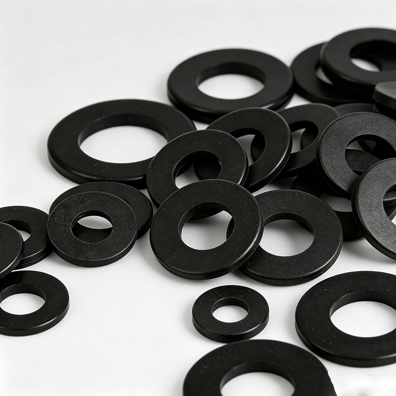
For a flat gasket, dimensions commonly include inside diameter, outside diameter, width, thickness, and bolt-hole dimensions where applicable. For a groove-mounted elastomer seal, the critical parameters may instead be groove width, groove depth, seal cross-section, compression, stretch or interference, and clearance.
I learned this lesson the hard way on an automotive project. The customer asked for a "gasket" without specifying the sealing mechanism. Our team calculated dimensions for a flat gasket. The customer expected a molded seal with specific compression characteristics. Both calculations were technically correct, but they produced completely different parts.
The first question should always be: What sealing geometry are we actually calculating? If this isn't established, even a technically correct formula can produce the wrong part.
Here's how different gasket types require different calculation approaches:
Flat Gaskets: Focus on radial width, thickness, and sealing land coverage. Calculate: OD = ID + 2 × gasket radial width.
O-Rings: Calculate groove dimensions, compression ratios, and stretch percentages. Standard groove calculations apply.
Molded Seals: Consider cross-section geometry, compression set, and mating surface requirements.
Foam Gaskets: Account for compression recovery, cell structure, and deflection characteristics.
Custom Profiles: Design around specific sealing mechanisms and mating geometries.
How Do You Calculate Flat Gasket Dimensions Correctly?
For a simple annular flat gasket, the basic relationship is straightforward, but determining the correct values requires engineering judgment.
The radial gasket width formula is simple: Gasket radial width = (OD - ID) / 2. The difficult part is determining the correct gasket radial width from your sealing requirements.
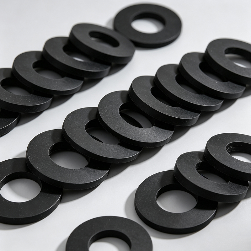
The mathematical formulas are: OD = ID + 2 × gasket radial width, or ID = OD - 2 × gasket radial width. These calculations are straightforward. The engineering challenge is determining the correct gasket radial width.
That dimension should come from the available sealing land and required sealing coverage, not from an arbitrary value added to the opening. If the sealing surface provides a certain radial width, the gasket should be positioned to adequately cover the intended sealing area without interfering with adjacent structures.
This means the calculation starts with the sealing interface, not the rubber dimensions. I always tell my team: "Design the gasket for the sealing surface, not for the opening."
Here's my systematic approach for flat gasket calculations:
Step 1: Measure the actual sealing surface width, not just the opening. Step 2: Determine required sealing coverage based on pressure and application. Step 3: Check clearance to adjacent structures and bolt holes. Step 4: Calculate gasket width with safety margin for positioning tolerance. Step 5: Verify the gasket can be manufactured within required tolerances.
The key insight is that gasket width affects sealing effectiveness. Too narrow provides insufficient coverage. Too wide can interfere with assembly or extend beyond the sealing land.
Why Is Thickness More Critical Than ID and OD?
A gasket can have perfect inner and outer dimensions and still fail completely because its thickness is wrong.
Thickness directly controls compression during assembly. The compression relationship is: Compression (%) = (Original thickness - Compressed thickness) / Original thickness × 100%
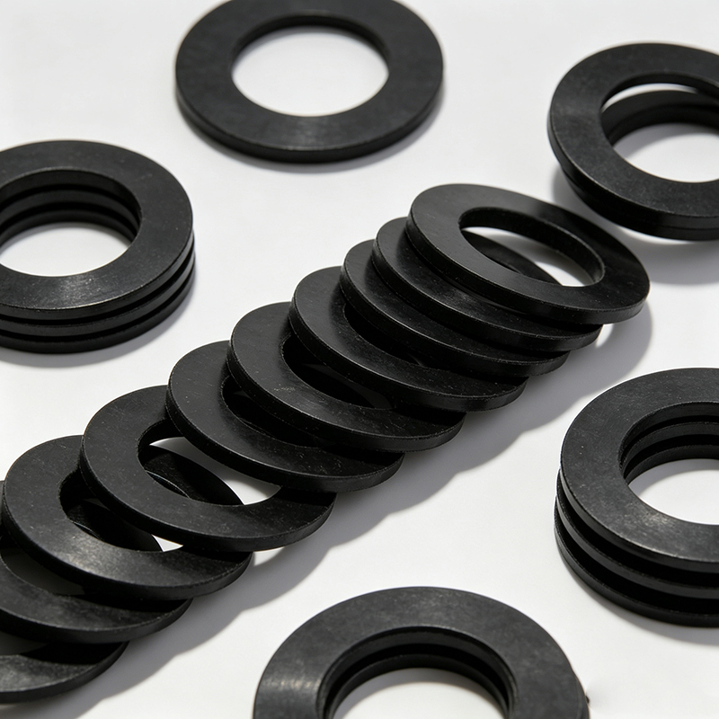
For example, if a gasket has an original thickness of 3.0 mm and the assembled condition compresses it to 2.7 mm: Compression = (3.0 - 2.7) / 3.0 × 100% = 10%. The calculation is simple. The engineering decision is complex.
The appropriate compression range depends on gasket material, geometry, application, sealing mechanism, and design standards. Different materials require different compression levels. EPDM rubber typically needs 15-25% compression for effective sealing. Silicone may require different values. Foam gaskets have entirely different compression characteristics.
I once worked on a medical device project where we used the "standard" 2mm thickness because it was common in other products. During environmental testing, some units leaked while others passed. The investigation showed that our 2mm thickness created compression variations from 8% to 28% depending on manufacturing tolerances. Some units had insufficient compression for sealing. Others were over-compressed and took permanent set.
The project should not begin with "We normally use a 2mm gasket." It should begin with "What compression condition is required for this specific sealing system?"
Here's how I determine correct thickness:
- Identify minimum compression needed for sealing
- Determine maximum compression before material damage
- Calculate manufacturing tolerance stack-up
- Select thickness that keeps all units within the functional window
- Validate with actual hardware testing
How Do Manufacturing Tolerances Affect Your Calculations?
A nominal gasket dimension represents only one condition. Mass production creates variation that can push your design outside the functional window.
The most important calculation is often the tolerance calculation. You must ensure both minimum and maximum compression conditions remain within acceptable ranges.
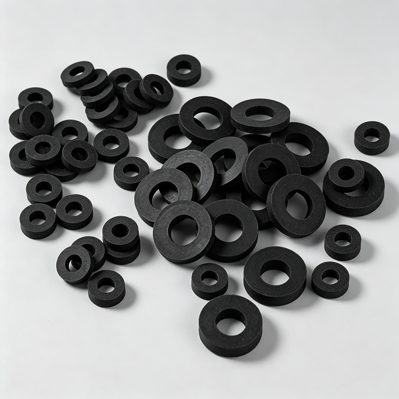
Consider the tolerance sources: gasket thickness tolerance, groove-depth tolerance, flange flatness variation, and mating-component tolerance. The actual compression will differ from nominal design. The project should evaluate minimum compression condition and maximum compression condition.
The objective is ensuring: Minimum actual compression ≥ minimum required sealing compression, and Maximum actual compression ≤ maximum acceptable compression. If this relationship isn't satisfied, the design has no manufacturing margin.
This is why prototypes can pass while mass production fails. Prototypes often have favorable dimensional combinations. Production introduces normal variation.
I learned this on an industrial equipment project. The customer provided housing opening dimensions, gasket nominal ID, OD, thickness, material family, and sealing requirements. We manufactured according to the drawing. First samples passed dimensional inspection and assembled successfully on prototype housing. The project team approved tooling for mass production.
Several weeks later, production assembly required noticeably greater assembly force on some housings. After environmental testing, leakage appeared on a portion of finished units. The first reaction was "The gasket dimensions must be wrong." Investigation showed gasket dimensions were within drawing requirements. The problem was that drawing requirements didn't adequately control actual compression conditions.
| Condition | Compression Result |
|---|---|
| Best case | 18% - Good sealing |
| Nominal | 15% - Acceptable |
| Worst case | 8% - Insufficient sealing |
The prototype had favorable dimensional combination. Production parts didn't. The gasket was dimensionally compliant but not consistently functionally compliant.
What's the Complete Process for Robust Gasket Sizing?
A reliable gasket-sizing process requires systematic engineering analysis, not just dimensional calculation.
Follow these steps: Define sealing boundary → Determine sealing width → Calculate thickness → Analyze assembly conditions → Check manufacturing feasibility.
Step 1 - Define the sealing boundary: Determine what opening must be sealed, where the actual sealing surface is, what area the gasket must contact, whether the gasket is static or dynamic, and if there's internal or external pressure. Don't calculate from opening dimension alone.
Step 2 - Determine available sealing width: Identify usable sealing land. The gasket must fit within available area while providing sufficient sealing coverage. For annular gaskets: Radial gasket width = (OD - ID) / 2. But check selected radial width against actual flange geometry.
Step 3 - Determine required thickness: Select thickness based on sealing mechanism and available compression. For compressed gaskets: Required compression = original thickness - assembled thickness, or Compression ratio = compression amount / original thickness. Check target against applicable material and design requirements.
Step 4 - Calculate actual assembly condition: Don't stop at nominal dimensions. Calculate nominal condition, minimum-compression condition, and maximum-compression condition. Include relevant component and gasket tolerances.
Step 5 - Check manufacturing feasibility: Review calculated dimensions against rubber shrinkage, mold tolerance, flash, parting line, material dimensional stability, and critical functional dimensions. Theoretical dimensions aren't automatically manufacturable production dimensions.
This process requires more upfront engineering work but significantly reduces production risk. I've seen too many projects that skipped tolerance analysis and paid the price in production delays and customer complaints.
Conclusion
Calculating gasket size correctly requires engineering analysis, not just measuring openings and adding width. Success depends on understanding your sealing system completely before picking any numbers.